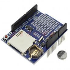
The datalogger shield has a few things to make it an excellent way to track data
Top Left - There's a real time clock (RTC) which has a chip, crystal, and backup battery for up to 7 years of timekeeping
Middle Left - an on-board 3.3V regulator keeps the shield's 3V parts running smoothly. There's also a green PWR (Power) good LED
Top Middle - A big SD card holder can fit any SD/MMC storage up to 32G and and small as 32Meg. If you have a MicroSD card, there are low cost adapters which will let you fit these in. SD cards are tougher to lose than MicroSD. Simply Push or Pull the card into this slot
Top Right - We have two user-configuratble LEDs. Connect a wire from any Arduino pin to L1 orL2 marked pads and pull high to turn on LED1 or LED2
A reset button will reset the entire Arduino, handy for when you want to restart the board
Middle - A level shifter keeps the SD card safe from the potentially-damaging 5V signals from the Arduino. It will work with 3V signals as well.
We also have some extra breakouts shown above, around the breakout board area
- 3V - this is the 3V out of the regulator. Its a good quality 3.3V reference which you may want to power sensors. Up to 50mA is available
- SQ - this is the optional Squarewave output from the RTC. You have to send the command to turn this on but its a way of optionally getting a precision squarewave. We use it primarily for testing
- WP - this is the Write Protect pad on the SD card, you can use this to detect if the write-protect tab is on the card by checking this pin
- CD - this is the card detect pad on the SD card. When this is connected to ground, an SD card is inserted. We suggest using the internal pullup on an Arduino pin if you want to use this pad
- CS - this is the Chip Select pin for the SD card. If you need to cut the trace to pin 10 because it is conflicting, this pad can be soldered to any digital pin and the software re-uploaded
- L2 and L1 - these are optional user-LEDs. Connect to any digital pin, pull high to turn on the corresponding LED. The LEDs already have 470 ohm resistors in series.
Se https://learn.adafruit.com/adafruit-data-logger-shield/overview


